Appendix X.
Glider Loading and Lashing Diagrams. June 1944.
Volume I. Part 3. Section 2.
Horsa Mk I, loading diagrams.
General Instructions.
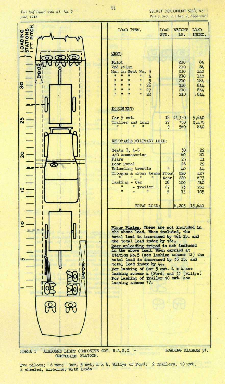
1). The accompanying loading diagrams give details of the correct positioning in the Horsa glider of various combinations of military equipment, and the load stations, weights, and load indexes of the components of these loads.
2). With each glider is supplied a loading chart, the method of using of which is described in A.P. 2453D, Volume I, Part 3, Section 2, Chapter 2. These loading diagrams are complementary to the glider loading chart and are intended to facilitate a rapid pre-flight check of the C.G. when these particular loads are to be carried.
3). Any variation from the loads stipulated must be accounted for when checking up with the glider loading chart. The publication of these diagrams does not absolve the loading officer from the responsibility of ensuring that the weights quoted are correct and that the aircraft C.G. is within permitted limits at the time of take-off.
4). It is essential that the equipment offered for loading is checked to ensure that it corresponds to the item as listed in this publication.
5). On the loading diagrams will be found references to lashing schemes. These lashing schemes are contained in Appendix I to Chapter I of this Section and consist of detailed diagrams showing the correct methods of lashing loads into the glider.
Horsa Mk I. Loading Diagram 51. Jun 1944.
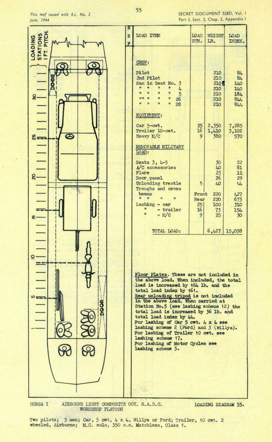
Horsa Mk I. Loading Diagram 55. Jun 1944.
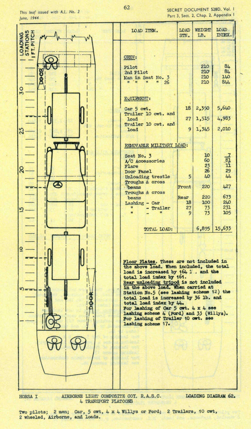
Horsa Mk I. Loading Diagram 62. Jun 1944.
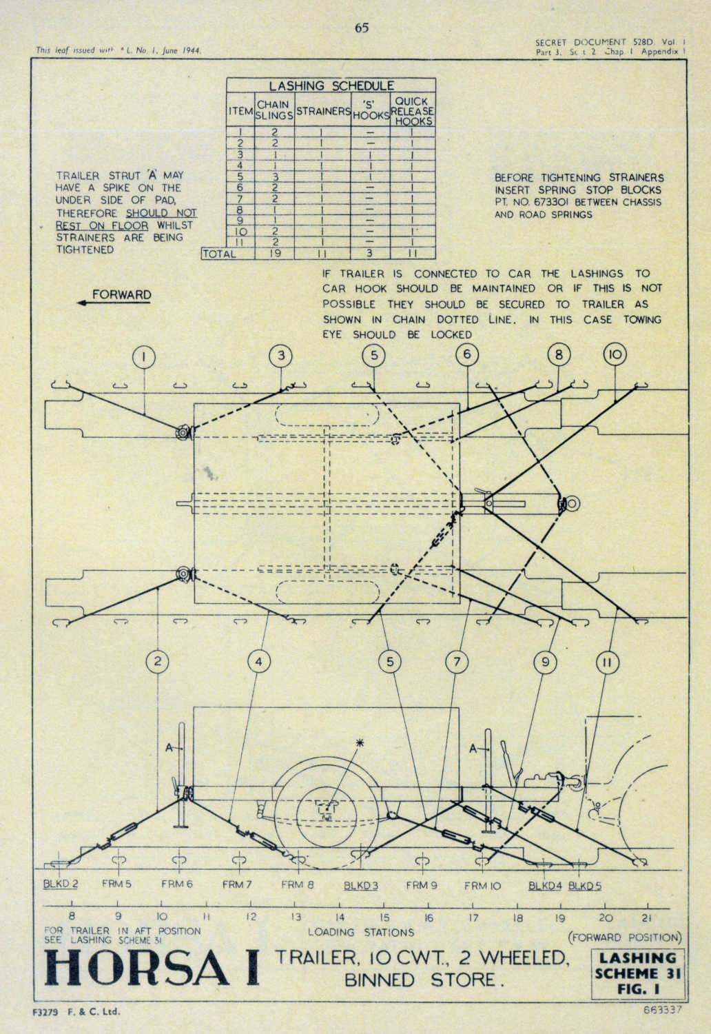
Horsa Mk I. Lashing scheme 31-1. Jun 1944.


